My first "computer mod" attempt!!
Hey, if you're going to make a custom
computer mod, might as well
start BIG!!
Mark's scanner
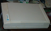
computer modification. Take an old Microtek scanner, and turn it
into a working computer!
This was my first scanner, way back in '97. "Scuzzy" interface, through an IDE "add-on" card, it cost me $300!! Within a year, it was outdated (nature of the beast, eh?), and replaced shortly thereafter with a new parrallel port pass-through scanner. Yeah, those were the days, of "hi-tech" computer peripherals!!
For whatever reason, I held onto this old dinosaur, and when I saw my buddy Chris, of KiSA mods and designs doing some of his wild custom modifications, I just had to try one of my own. Like I said earlier, if you're going to make a first custom mod, might as well start big, and scanners don't get much bigger than this old behometh! What I wanted was something that would be a fully functional computer mod, capable of normal day to day computer tasks, that would look as much like a scanner from the outside as possible. Of course, that's nearly impossible from every angle, but I'm fairly happy with the results.
The computer inside:
Biostar M7VIQ socket A motherboard (picked up as a fully functional refurb from Newegg), with
onboard video, audio and LAN
AMD Athlon XP1700+ OEM cpu with a Thermaltake Volcano 10 heatsink (original fan replaced
with higher cfm 60mm fan)
256mb pc2100 DDR ram
Maxtor 30gb 7200rpm hard disk drive
Lite-On 52x24x52 speed CDRW drive
Turbo-Cool 200watt rack 1-U power supply (kick-ass p/s I purchased from MPJA .....highly
recommended for small space power supply you might need for a mod like this one). The only
down side to this power supply that I found was that the 20-pin atx motherboard connector had
really short wires, since it's normally used for rack mount systems.
2 black rounded IDE cables, black mesh cable wrap, black molex connectors, and a 12" extension
cable for the 20-pin atx motherboard connector (the best price I found for one of these was at
3D Cool , for $8 + shipping), plus a couple 50mm fans I borrowed from a batch of old socket 7
cpu coolers I had laying around.
Motherboard tray, power and hard drive led connectors, and power & reset switches from a junk
case I had laying around the house.
A 12-inch white cold cathode light kit (hey, I wanted this thing to at least resemble a scanner still,
when I lifted the lid!!).
My first challenge was to gut the scanner. With a little time, that was accomplished, along with my first disappointment.....there was no way I could keep the machinery inside that moved the light bar back and forth, and still get the computer to fit inside. :(
Oh well....once I had the "case" gutted, I had to figure out how to fit everything I wanted inside. Let's see how this looked.


The first pic is of the
scanner "case" from the right side. This is the side I wanted to
keep "clean", so that it would still look somewhat like a
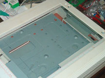
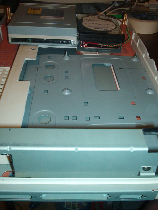
scanner. The second pic is of the inside of the case, looking
through the "window" of the scanner's glass top, showing the
motherboard tray in place, and the cdrw and hard drives already
mounted. Unfortunately, it also showed me my second
disappointment..... the hardware used to hold the scanner lid in place
(and make it removeable for large or thick objects to be scanned)
wouldn't work with the power supply I was using. Future thinking
cap ops were to be in order!! ;)
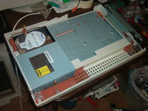
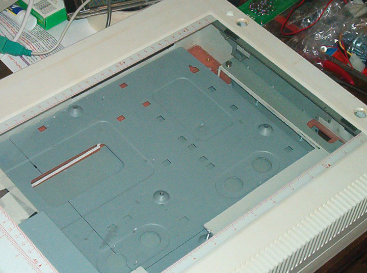
The third pic shows the inside of the case, and gives you an idea of how tight things were already getting! The motherboard I used is fairly small, but it's still an ATX mobo, and not a micro, so it took up a bit of space!! In order to get the mobo to fit low enough in the case, and in order to allow for the cpu and heatsink/fan combo to fit under the glass, I had to cut below the plastic surface inside the scanner, and utilize the area below, that originally had the electronics of the scanner mounted inside. Because of that, I decided to use the motherboard tray, versus just mounting the mobo to the case, since then I didn't have to worry about the mobo grounding on the metal portion of the lower case. It cost me only about 1/4" of height inside. :)
The fourth pic shows the case from the back, and gives you an idea of how the cdrw and hard drives are mounted. I custom fit both of them, my modding some brackets I had leftover from other projects. I especially wanted to have a hard drive cooler under the hard disk, since I knew cooling inside the case was going to be minimal (to help keep the "clean side" clean).
Once I had all the equipment fitted up inside the case, the rest of it was just a matter of fitting a couple fans for exhaust, drilling the holes for the power and hard drive LED's, and cutting the hole for the power and reset switches. Then fit up the power supply and "back panel" cutout, and figure out how the top half of the case and the lid were going to be attached. Easy, eh??